
This is my first post in English, so please excuse me if I have mistakes in redaction. The idea is to continue improving with each publication.
My goal is to develop a VFO based on DDS and PIC microntroller for the famous QRP kit Iler 40 (by Spanish amateur radio EA3GCY). Originally, this kit uses VFO with a variable capacitor (polyvaricon) to control frequency, with a range about 30kHz to 50kHz (portion of 40 meter band). EA3CGY offers a very effective DDS kit that lets use the entire band, but I decided to built my own version with more functions that are not considered on this kit. This is my homebrew Iler 40 QRP. In this post, I´ll show you schematics, give .hex program to load in microcontroller and advices to complete the transceiver.
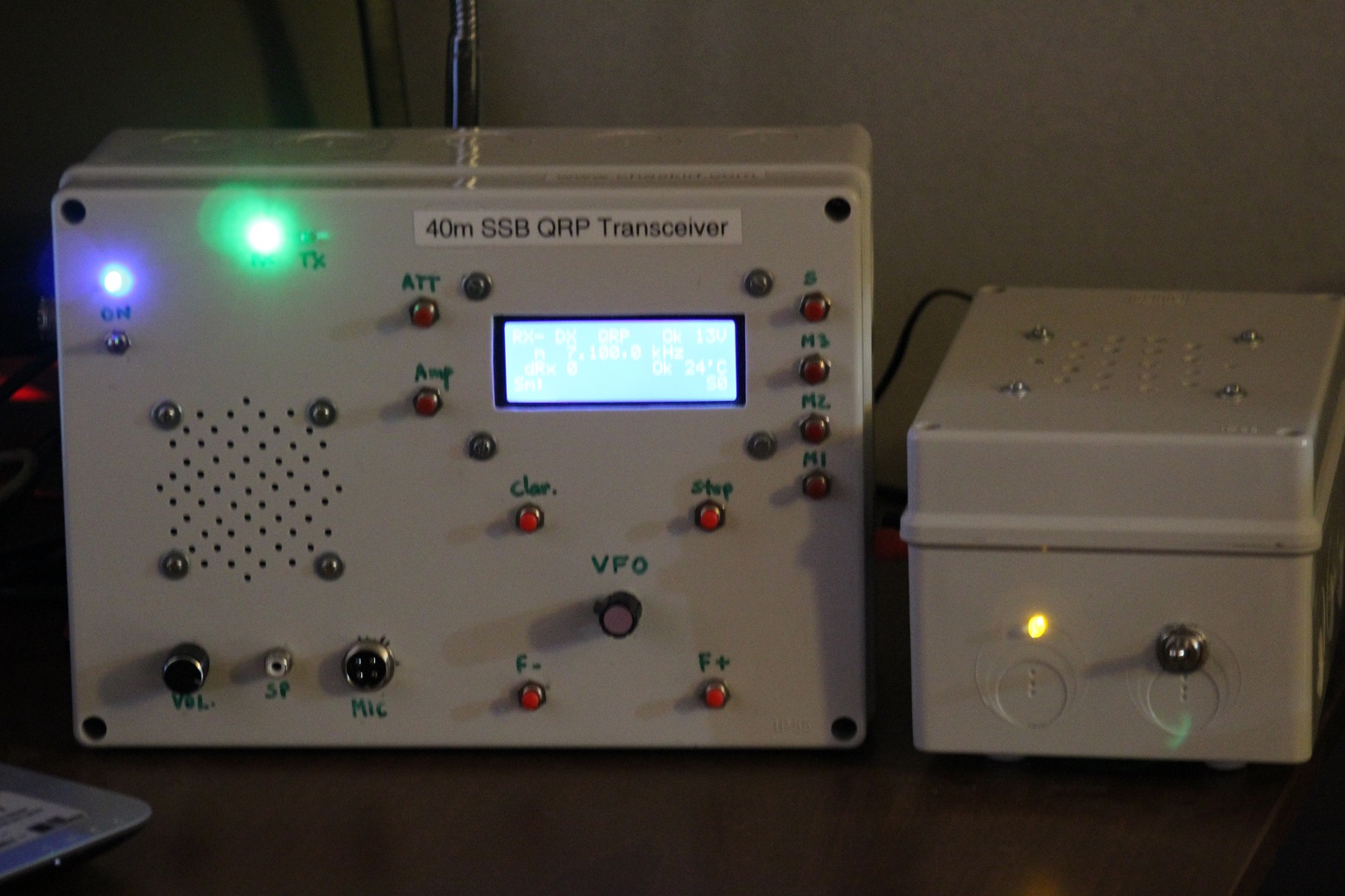
My version include:
-
- Rotary encoder knob to control frequency, in steps of 0.1kHz, 1kHz and 5kHz, selected by push button.
- Up and Down push button to move frequency with accuracy.
- SSB receiver clarifier. It permit to move frecuency in receiver RX mode, without affect transmission TX frequency (RX offset). With this function we can to receive stations with TX frequency shift.
- 3 easy access and save/erase frequencies memories (M1, M2 and M3), loaded to internal flash memory in the microcontroller.
- Digital thermometer, directly in contact with power stage heat sink. In future, I´ll build a litle circuit to control a fan to dissipate heat, special to use in a large QSOs.
- ATT (RX attenuation for receive local stations) and AMP (PTT to switch RX/TX external linear amplifier), both controlled by push buttons.
- RSSI RX display with barrs and S-scale direct lecture.
- DC supply voltmeter, with indicator Low, Good or High.
I implemented the idea showed in Fig. 2. I have my Iler 40 kit without VFO coil L6 (to eliminate oscillator stage), and a DDS module generates VFO RF signal. For more information about DDS fundamentals, you can view my post about it (only in Spanish, at yet).
This DDS VFO requires a frequency offset of 4913,52 kHz (defined by pass frequency of SSB filter in Iler 40 PCB). When I turn on my QRP, I can adjust this offset if it would be neccessary (I have to push one button to access offset configuration… but now I don´t remember wich button, jejejeje… it could be ATT button… as soon as possible I will complement this information, or you can try with all of them).
If you want to build this version QRP Iler 40, you would read this document about connection between Iler 40 and external DDS VFO.
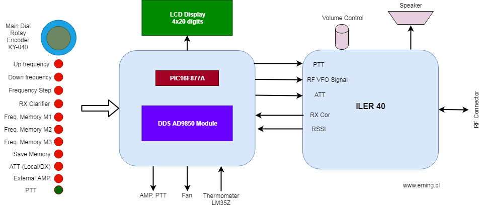
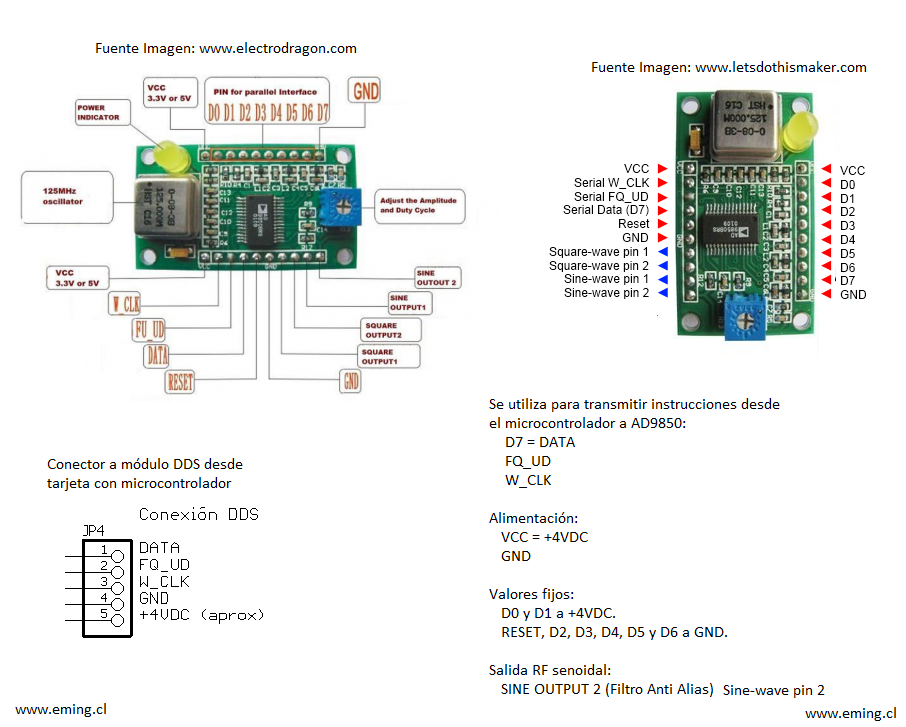
Fig. 3 shows schematic of control unit, and Fig. 4 let to know pinout used un this setup. In Fig. 5 you can see how to connect rotary encoder and push buttons.
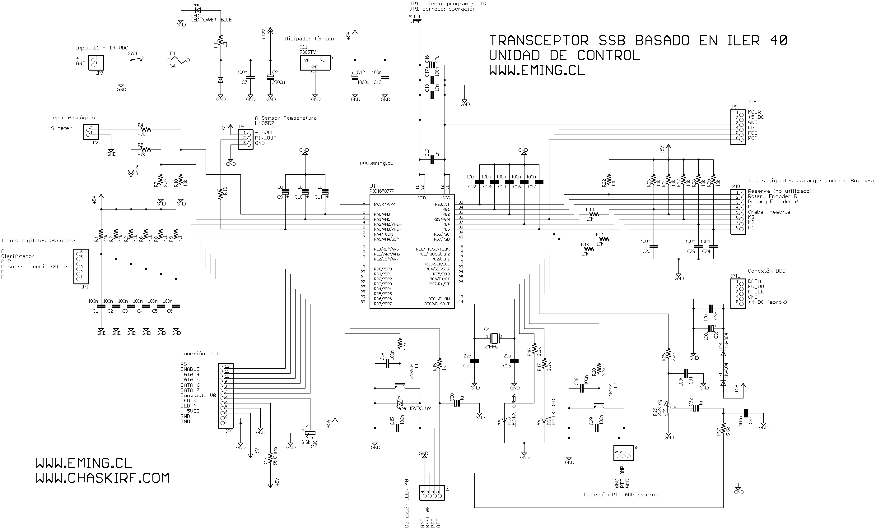

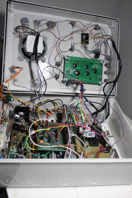
It´s neccesary to avoid long wires with digital signals close to Iler 40 board, because RX stages are sensitive to EMI. Special care with LCD wires. Usefull idea would be to put both PCBs (Iler 40 and control unit + LCD) in different metallic boxes (Faraday´s boxes), with RF wires with ground shield (coax) and digital ones as short as possible, and far to analog wires.
To program PIC16F877A, download this .HEX file and upload to PIC microcontroller with your favorite programmer (I´m using PiCkit 3). While you are programming this target, jumper J6 must to stay open. After load software, close it.
Download .HEX file to load in PIC16F877A
In this video, I made a RX test, usign a End Fed Half Wave antenna put at 2 meter above the floor. When I put my phone (camera) close this transceiver, EMI produce noise.
Because my antenna is no ideal (SWR too high) in this video, I don´t used TX mode (PTT stayed open), but with dummy load and my NISSEI RS-50, I metered output power about 4W P.E.P., when supply voltage is about 12.5 [V].
I really love this QRP kit (to buy one, visit www.qrphamradiokits.com), and with my control unit & VFO is perfect for me!!.
I´m glad to receive your comments.
Best regards (73´s),
Emerson
CD3EMT